Today we are going to learn about a new sensor of the stm32f3 Discovery Board. This sensor is known as Gyroscope. We are going to know about this particular sensor and its function and why we need it in our embedded development. This is going to be a series of the blogs just like other series for Sensors.
In our previous series of blogs, we have discussed the Accelerometer sensor and how we can make a Punch-o-meter using this sensor. You can visit those parts of the series from here->> PART 1, PART 2, PART 3.
As we are working with the Embedded Systems they make our task fast and reliable. Also, they are much smaller in size compared to traditional computers, which makes them compact and portable, and useful for mass production. Management of Embedded Systems is pretty easy, as elements used in their creation are cheap & long-lasting. Embedded Systems are also cost-effective.
Gyroscope
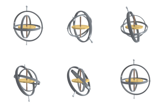
A gyroscope is a device used for measuring or maintaining orientation and angular velocity. It is a spinning wheel or disc in which the axis of rotation (spin axis) is free to assume any orientation by itself. When rotating, the orientation of this axis is unaffected by tilting or rotation of the mounting, according to the conservation of angular momentum.

Where do we need a gyroscope?
Gyroscope, this device contains a rapidly spinning wheel or circulating beam of light which we use to detect the deviation of an object from its desired orientation.
Gyroscopes are uses in compasses and automatic pilots on ships and aircraft, in the steering mechanisms of torpedoes, and in the inertial guidance systems installed in space launch vehicles, ballistic missiles, and orbiting satellites.
Gyroscope Sensor

The other name for gyroscope sensor is Angular Rate Sensor or Angular Velocity Sensor. We can install these sensors in applications where the orientation of the object is difficult to sense by humans.
It is a device that can measure and maintain the orientation and angular velocity of an object.
Working of Gyroscope
The sensor is able to measure the motion of an object. Now to measure more accurate motion readings gyroscope is combined with the other sensor and that is an accelerometer.

Depending on the direction there are three angular rate measurements. Yaw- the horizontal rotation on a flat surface when we see the object from above, Pitch- Vertical rotation when we see the object from front, Roll- the horizontal rotation when we see the object from front. So these are the three measurements we saw using a gyroscope sensor.
Discovery Board and Gyroscope Sensor
As you all know that we are working on this stm32f3 discovery board. So stm32f3 board contains multiple sensors including the gyroscope sensor. Now using this sensor of the board we are going to get the readings of the gyroscope sensor and we are going to print those measurements on the itm console.
Now to access this sensor of the stm32f3 Discovery Board we are required to pass some levels. So let’s start with that.
Access the Gyroscope on the stm32f3 Board
To access the sensor on the board we need to include some dependencies in the project.

[dependencies]
cortex-m = "0.6.3"
cortex-m-rt = "0.6.3"
panic-itm = "0.4.0"
stm32f3-discovery = "0.6.0"
l3gd20 = "0.3.0"- cortex-m here is for providing the core peripherals
- cortex-m-rt is for providing the entry attribute
- panic-itm to control the panic of the project
- stm32-discovery to provide the peripherals and features of the discovery board
- l3gd20 this is the main crate here which is going to provide us with the way to access the gyroscope sensor of the board. With this crate only we are going to get the readings of the board
After this, we are going to provide the initialization of the code.
Now we are going to access the peripherals and clocks of the core and device. We can do it using this.
    let core_peripherals = cortex_m::Peripherals::take().unwrap();
    let device_peripherals = stm32::Peripherals::take().unwrap();

    let mut flash = device_peripherals.FLASH.constrain();
    let mut rcc = device_peripherals.RCC.constrain();

    let clocks = rcc.cfgr.freeze(&mut flash.acr);
Here we are able to access the core and device peripherals with the clock. The next thing we have to do is to access the port to access the pins. We need to access the pins of the gyroscope register and the led registers so that we can work on them.
let mut gpioe = device_peripherals.GPIOE.split(&mut rcc.ahb);
let mut gpioa = device_peripherals.GPIOA.split(&mut rcc.ahb);
Okay, we are done till here, we are not going to stretch it furthermore in this part only. We will continue the series with the next part of the gyroscope.
Thanks for reading. Keep learning…
If you want to read more content like this? Subscribe to Rust Times Newsletter and receive insights and latest updates, bi-weekly, straight into your inbox. Subscribe to Rust Times Newsletter: https://bit.ly/2Vdlld7.


1 thought on “Gyroscope| Sensor of the “stm32 Discovery Board”5 min read”
Comments are closed.